Slide Set
Bio-eye Surgical Presentation Slide Set
Contains surgical photos. Click ![]() to expand the slide set page. Click a photo to enlarge view.
to expand the slide set page. Click a photo to enlarge view.
1. Problems With Orbital Implants:
- Migration
- Extrusion
- Motility
- No support for artificial eye
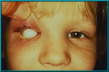 2. Young girl with an extruding silicone implant. Hornblass’s survey of over 5000 implant cases revealed an extrusion rate of 9 to 42% for silicone- and PMMA-type implants.
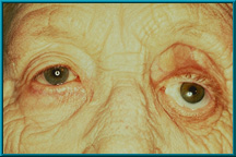
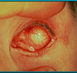 3. Silicone implant that has migrated superiorly and temporally. Hornblass’s survey of over 5000 implant cases discovered a migration rate of 16 to 61% for silicone- or PMMA-type implants.
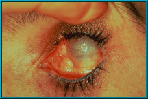 4. Spherical implant that has migrated superiorly and temporally. Hornblass’s survey of over 5000 implant cases discovered a migration rate of 16 to 61% for silicone- or PMMA-type implants.
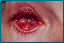
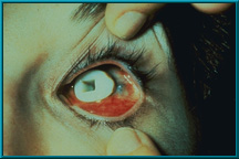
 5. Extruding silicone implant. Hornblass’s survey of over 5000 implant cases discovered an extrusion rate of 9 to 42% for silicone- and PMMA-type implants.
 6. Extruding partially buried-type implant. Hornblass’s survey of over 5000 implant cases discovered an extrusion rate of 9 to 42% for silicone- and PMMA-type implants.
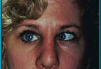
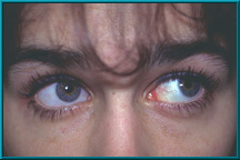
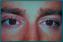
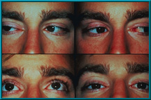
 7. Patient demonstrating poor motility in superior gaze. Hornblass’s survey of over 5000 implant cases discovered a poor-motility rate of about 50% for silicone- and PMMA-type implants.
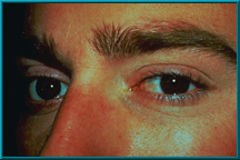
 8. Normal appearance of a socket following closure of the conjuctiva. The socket should look similar to that with a silicone or mehthyl-methacrylate spherical implant after closure of the conjuctiva. The purple dot on the patient’s conjuctiva is placed to show the extreme movement possible with the Bio-eye orbital implant.
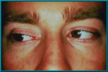
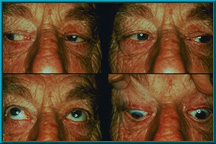
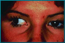 9. Patient demonstrating poor motility in temporal gaze. Hornblass’s survey of over 5000 implant cases discovered a poor-motility rate of about 50% for silicone- and PMMA-type implants.
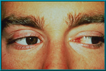
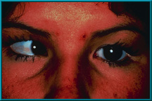 10. Same patient demonstrating poor motility in medial gaze. Hornblass’s survey of over 5000 implant cases discovered a poor-motility rate of about 50% for silicone- and PMMA-type implants.
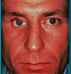
11. Patient with sagging right lower eyelid secondary to long-term wearing of an artificial eye without support from a motility/support peg. Hornblass’s survey of over 5000 implant cases revealed a lower lid-malposition rate of 5 to 24% for silicone- and PMMA-type implants.
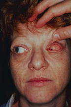
 12. Female patient with a severely dropped socket. Note marked superior sulcus defect and severe laxity of the lower eyelid. Hornblass’s survey of over 5000 implant cases revealed a lower lid-malposition rate of 5 to 24% for silicone- and PMMA-type implants.
13. Why old integrated implants failed
- Violated basic surgical principle
- Foreign material exposed
- Wound could not re-epithelialize
- Chronic infection-extrusion
 14. Extruding Stone-Jordan implant. This complication was common with these partially buried and partially exposed implants.
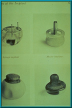 15. Other types of the older integrated orbital implants. Clockwise from top left: Arruga implant, Moore implant, Cutler implant, Rosenthal implant.
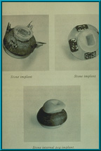 16. Several different types of the old integrated implants which were partially buried and partially exposed. These implants were all developed by Stone.
17. Comparison of Implant weights
       HA     Silicone  Acrylic

16mm   2.1      3.4       3.4

20mm   2.8      4.8       4.9

22mm   4.7      6.3       6.5
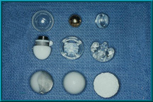 18. Implant variations used over the years. The implant in the upper left is a hollow glass ball, as first used by Mules in 1884. Also shown are implants of gold, silicone, and acrylic in various shapes. Middle left: a Troutman implant containing a magnet to hold the artificial eye. Bottom right: the Bio-eye Hydroxyapatite Orbital Implant.
19. Advantages of the Bio-eye Hydroxyapatite Orbital Implant
- Decreased migration
- Decreased extrusion
- Increased motility
20. Advantages of the Bio-eye Hydroxyapatite Orbital Implant
- Support prosthesis via peg
- Gives flexibility for fitting prosthesis to help (prevent) ptosis and superior sulcus deformity
21. Concept
- Vascularized implant can be exposed without extrusion
22. Concept
- Vascularized implants will be more stable.
- i.e. less migration and extrusion
23. Why the Bio-eye Hydroxyapatite Orbital Implant works
- Natural substance that becomes vascularized
- When exposed will re-epithelialize
24. Bio-eye Hydroxyapatite Orbital Implant
- Released by United States FDA for use as an orbital implant in August 1989.
- Animal studies were done using hydroxyapatite implants from 1983 to 1985, followed by an FDA clinical trial conducted between 1985 and 1989.
25. Hydroxyapatite
- Bio-compatible
- Bio-active
- Non-toxic
- Non-carcinogenic
- Non-allergic
- Non-inflammatory
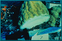 26. Photo of a piece of ocean coral, from which hydroxyapatite is derived.
27. Hydroxyapatite [chemical formula for hydroxyapatite]
Complex inorganic calcium salt that makes up the primary mineral portion of human bone
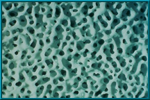 28. High-powered magnification of hydroxyapatite.
29. Hydrothermal Exchange Reaction
[chemical formulas for coral and hydrocyapatite]
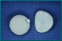
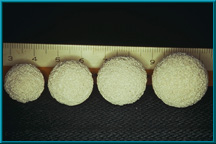 30. Sterile implants with Conformer available in:
16mm, 18mm, 20mm, 22mm
 31. An artist’s illustration of the hydroxyapatite material prior to ingrowth of vascular tissue.
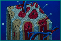 32. Artist’s illustration of the hydroxyapatite material after ingrowth of vascular tissue. When placed next to bone, new bone ingrowth occurs; when placed in soft tissue, such as in the orbit, new fibrovascular tissue ingrowth occurs.
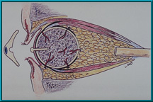
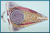 33. Illustration of the Bio-eye Hydroxyapatite Orbital Implant in an enucleated socket with the muscles attached. These muscles are attached in the same manner as with some silicone or methylmethacrylate (PMMA) implants.
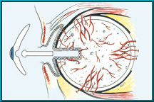 34. Illustration of the Bio-eye Hydroxyapatite Orbital Implant showing a peg hole drilled into the implant. Note conjunctival epithelium that lines the hole. Also note the blood vessels growing into the hydroxyapatite implant.
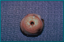
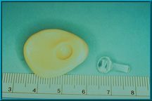
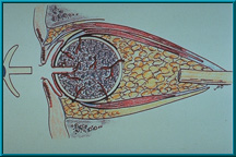 35. Hydroxyapatite Orbital Implant that has a peg hole to accept the motility/support peg. In this older configuration, the peg is attached directly to the artificial eye. This direct attachment made it difficult for patients to insert the eye. Recent technique favors a ball-and-socket coupling.
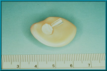
 36. Bio-eye Hydroxyapatite Implant using a peg attachment with a ball on its anterior aspect. This ball fits into an indentation on the back of the artificial eye creating a ball-and-socket coupling between the implant and the artificial eye. This variation allows the patient to easily insert the eye.
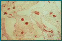 37. Histologic section of a rabbit implant. The clear area is hydroxyapatite prior to decalcification. The pink area is fibrovascular tissue that has grown into the pores of the hydroxyapatite. Blood vessels filled with red blood cells are visible. There is essentially no inflammatory reaction and no foreign body giant cells.
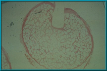 38. A histologic specimen slice taken through the peg hole of the Bio-eye Hydroxyapatite Orbital Implant. The pink area outlining the porous hydroxyapatite is fibrovascular tissue ingrowth. The clear area is hydroxyapatite .
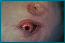 39. Rabbit showing an orbital implant with a prepared. Note the peg attached to the posterior of the conformer.
 40. Hydroxyapatite Orbital Implant harvested from a rabbit prior to histologic sectioning.
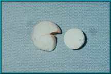 41. A Bio-eye Hydroxyapatite Orbital Implant prior to being placed into a scleral wrapping.
 42. A Bio-eye Hydroxyapatite Orbital Implant wrapped in a scleral shell. The sclera is sutured closed prior to inserting the implant into the orbit.
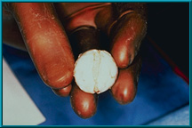
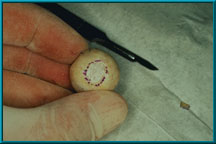
 43. A dot marked on the sclera designates the anterior projection of the implant. Note windows cut in the sclera to facilitate attachment of the extraorbital muscles. The highly vascular muscles encourage rapid vascular ingrowth where they contact the implant.
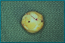
 44. The sclera has been cut away from the posterior aspect of the implant to increase contact between orbital tissues and the implant. The purpose of cutting windows in the sclera and exposing a section of the posterior portion of the implant is to encourage more rapid vascularization of the implant.
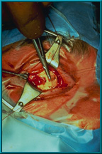 45. A rectus muscle being attached to a window in the sclera. The site of muscle attachment becomes a point of origin for vascular tissue ingrowth into the pores of the hydroxyapatite material.
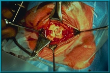 46. All four muscles have been attached to the sclera. Typically, only the four rectus muscles are attached. The oblique muscles can be attached according to the surgeon’s preference.
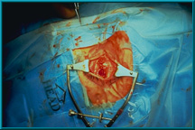 47. The conjunctiva has been closed following standard procedures. Tenon’s capsule and the conjunctiva should be closed as separate layers to prevent early exposure of the rough hydroxyapatite material.
 48. Normal appearance of a socket following closure of the conjunctiva. The socket should look similar to that with a silicone or methyl-methacrylate spherical implant after closure of the conjunctiva. The purple dot on the patient’s conjunctiva is placed to show the extreme movement possible with the Bio-eye orbital implant.
49. For information on Hole Placement in the Bio-eye Hydroxyapatite Orbital Implant, please refer to the Titanium Peg System Letter.
50. Caution:
– Don’t place the hole until the implant is vascularized
– T99 bone scan
– MRI with contrast and surface coil
The hole procedure should not be performed without established adequate vascular ingrowth. The vascularity of the implant is best determined by a bone scan or an MRI with a contrast agent.
51. Concept
- Motility and support are best with direct connection between implant and artificial eye
Direct coupling delivers all avalable movement to the artificial eye.
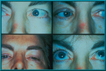 52. Composite photo showing the motility achieved in the first patient to receive a Bio-eye Hydroxyapatite Orbital Implant. This patient received the implant in 1985.
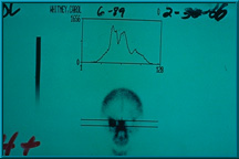
 53. Bone scan illustrating little or no uptake of technetium 99 into the implant, which indicates the presence of little or no fibrovascular tissue. In such cases, the implant is not ready to receive a motility/support peg. More time is required for the implant to vascularize further.
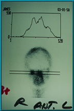
 54. Bone scan showing poor uptake of technetium 99 in the patient’s left orbit. The uptake in the left orbit is slightly less than the uptake in the right orbit. This would be graded 1+, and the implant is not ready for the hole placement.
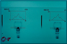
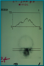 55. Bone scan showing adequate uptake of technetium 99 in the patient’s left orbit. The uptake is half way between that of the mid-facial bones (center peak) and the normal orbit, which is graded 2+, the minimum grade required for hole placement in the implant. The central peak always represents the mid facial bones.
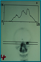
 56. Bone scan showing good uptake of technetium 99 in the patient’s right orbit. The uptake is equal to that of the mid facial bones. This is graded 3+, and this implant is ready for a peg hole placement. A grade of only 2+ is required for hole placement in the implant.
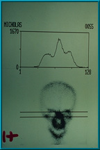
 57. Bone scan showing excellent uptake of technetium 99 in the patient’s left orbit. The uptake is graded 4+, since it is higher than that of the mid-facial bones.
 58. Bone scan showing excellent uptake of technetium 99 in the patient’s right orbit. This is graded 4+. A grade of only 2+ is required for peg hole placement in the implant.
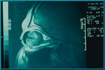 59. An MRI with gadolinium contrast agent showing the uptake in a Bio-eye orbital implant. The peg hole and artificial eye appear as dark regions in this scan.
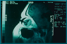 60. An MRI with gadolinium contrast agent showing the uptake in a Bio-eye orbital implant. Note robust vascularization in the posterior portion of the implant and around the peg hole.
 61. An artificial eye and a template made from the artificial eye. This template is used to mark the conjunctiva to indicate where to drill the hole for the motility/support peg.
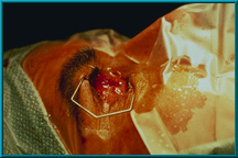
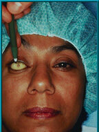 62. A patient with an artificial eye template in place. The location for the motility/support peg is marked through the hole on the conjunctiva.
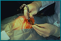
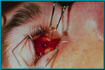
 63. Starting a pilot hole using a syringe needle in the area where the hole will be drilled for the motility/support peg. The pilot hole is made using graduated needles (21 to 16 gauge) to ensure proper angle of the final hole, which is made using a power drill.
 64. Drilling of the hole for the motility/support peg. In this case, a flexible corded drill is being used. Other drills are available for this procedure.
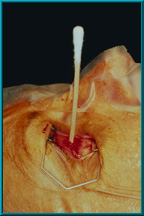 65. A patient in the supine position after the hole has been drilled for the motility/support peg. The shaft of a cotton-tip applicator has been placed into the hole to confirm that it is drilled perpendicular to the frontal plane of the patient. Proper angle is important for best results.
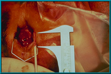 66. The shaft of a cotton-tip applicator is used to measure the depth of the hole for the motility/support peg. The hole should be drilled to a depth of 10 to 13 mm. The diameter of the hole will vary depending on the type of peg used: the sleeved peg requires a hole with a diameter of 3.8 mm; the standard peg requires a diameter of 3.0 mm.
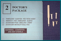 67. Two basic types of pegs are provided with each Bio-eye hydroxyapatite orbital implant: a flat-headed temporary peg and a ball-headed motility/support peg. A new locking-socket variation of the ball-headed peg is also provided with each implant, as are variations that incorporate a sleeve.
 68. After drilling, a temporary flat-headed peg is placed into the peg hole. The patient’s artificial eye is placed back into the socket and will be worn with the temporary peg for 1 month.
 69. The temporary flat-headed peg is replaced with a ball-headed motility/support peg. This peg should be placed into the hole immediately after removing the temporary peg to prevent tissue swelling. Swelling narrows the hole and makes it difficult to insert the peg.
 70. A well-seated motility/support peg. Note that only the ball head of the peg extends above the conjunctiva. This indicates a good fit.
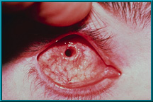 71. Desired result following the healing of a drilled peg hole. Note the quietness of the socket and the healthy tissue growing down the sides of the drilled hole.
 72. Desired result following the healing of a drilled hole. Note the quietness of the socket. There is healthy tissue growing down the sides of the drilled hole.
 73. Desired result following the healing of a drilled peg hole. Note the quietness of the socket and the healthy tissue growing down the sides of the drilled hole.
 74. Desired result following the healing of a drilled hole. Note the quietness of the socket. There is healthy tissue growing down the sides of the drilled hole.
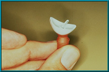
 75. A Bio-eye hydroxyapatite orbital implant fitted with a motility/support peg. The peg has been inserted into a hole in the implant; only the ball head of the peg is visible. Note the indentation in the back of the artificial eye to provide a ball-and-socket coupling.
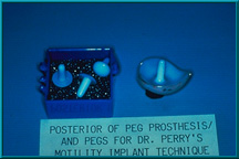 76. Several motility/support pegs. Right, shows peg resting on posterior of artificial eye. The peg can be glued directly to the eye if the eye is too thin to permit an indentation on its posterior surface. However, this configuration makes it more difficult for the patient to insert the eye.
 77. Ball-and-socket connection between the motility/support peg and the back of the artificial eye.
 78. Ball-and-socket connection between the motility/support peg and the back of the artificial eye.
 79. A ball-and-socket connection between the motility/support peg and the back of the artificial eye allows contact between the two components at all angles.
 80. A ball-and-socket connection between the motility/support peg and the back of the artificial eye allows contact between the two components at all angles. This is especially important in maintaining a natural appearance during extreme gaze.
 81. An enucleation patient showing excellent condition of the lids and sulci.
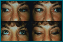
 82. An enucleation patient showing excellent motility. Also note excellent condition of the lids and sulci.
 83. An enucleation patient showing excellent motility. Also note excellent condition of the lids and sulci.
 84. An enucleation patient showing excellent motility. Also note excellent condition of the lids and sulci.
85. Indications for the Bio-eye hydroxyapatite orbital implant:
– Enucleation
– Evisceration
– Secondary implant
86. Indications for a secondary Bio-eye hydroxyapatite orbital implant:
– Movement of the artificial eye
– Migrated implant
– Extruded or exposed implant
– Treatment of enophthalmos
87. Enucleation
 88. An enucleation patient showing excellent motility. Also note excellent condition of the lids and sulci.
89. Evisceration
 90. An evisceration patient showing excellent motility. Also note good condition of the lids and sulci.
 92. A woman with a secondary Bio-eye hydroxyapatite orbital implant showing excellent motility. Approximately 12 years have passed between her primary enucleation and her secondary implant.
93. Hydroxyapatite Implants
Arthur C. Perry M.D. 5/85 - 8/91

Total Implants        141

  Enucleations         46    33%

  Eviscerations        19    13%

  Secondary            76    54%
94. Complications:
Extrusion 2 (1.4%)
– Acute infection – implants replaced
Exposures 8 (6%) 2 technique
– 3 Removed and replaced with HA
– 5 Covered and or healed
These are markedly low complication rates given historical trends for other orbital implants. A 1992 study by Hornblass showed traditional (Allen, Iowa, etc.) implants have a mean extrusion rate of 20% and a mean migration rate of 32%; with significantly lower motility.
95. Complications:
- Exposure of implant before vascularization
- Drilling of implant before vascularization
96. Complications of vascularized implant:
- No migration
- No extrusion
- No chronic infections
To date there have been no migrations, no extrusions, and no chronic infections in a well-vascularized hydroxyapatite implant; including those that have been drilled for the motility/support peg.
97. Exposure:
- Poor closure technique
- Implant too large
- Implant not deep enough in orbit
The implant surface is very rough. Good closure is essential to prevent erosion of Tenon’s capsule and the conjuctiva. This is one advantage of wrapping the implant in sclera or some other material.
98. Exposure:
- Implant not wrapped or capped
- Contracted socket
- Poor tissue quality – radiation
An implant must be of the proper size, and must be placed deep within the muscle cone. One of the few inhibitors of good vascularization is an orbit with compromised vascularity due to radiation treatment.
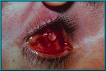
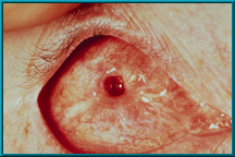
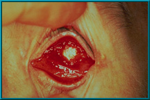
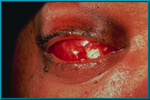 99. Exposure of hydroxyapatite prior to vascularization. The Bio-eye orbital implant must be treated as any other implant until it has vascularized. Only then can it deliver its most desirable characteristics: low-levels of migration, exposure, extrusion, and excellent motility via the motility/support peg.
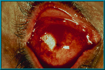
 100. Exposure of hydroxyapatite prior to vascularization. The Bio-eye orbital implant must be treated as any other implant until it has vascularized. Only then can it deliver its most desirable characteristics: low-levels of migration, exposure, extrusion, and excellent motility via the motility/support peg.
 101. Exposure of hydroxyapatite prior to vascularization. The Bio-eye orbital implant must be treated as any other implant until it has vascularized. Only then can it deliver its most desirable characteristics: low-levels of migration, exposure, extrusion, and excellent motility via the motility/support peg.
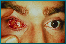
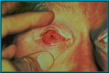
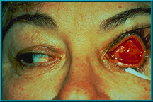 102. Patient showing spontaneous healing over an exposed area. Most small exposures heal over spontaneously. Large (5-6 mm) or growing exposures must be covered with some graft material (e.g., dermis, sclera, fascia), which should then be covered with a conjunctival flap for blood supply.
103. Factors that may influence vascularization:
- Wrapping implant
- Vascularity of orbit
- Drilling holes to center of implant
- Medical status of patient
One of the few inhibitors of good vascularization is an orbit with compromised vascularity due to radiation treatment.
104. Summary:
- Results have validated concepts
- Well-vascularized implant should last a lifetime and give best motility
- No extrusion or migration
- Support artificial eye
The original hopes for this unique implant have all been validated by experience.